
Technical Information & Designation
Understanding the model numbering system and technical specifications of PMK ball screws is essential for selecting the right component for your machinery.
1. Model Number Configuration
The PMK designation system combines several technical parameters into a single string. Use the guide below to decode your product name.
Nut Type Code
- Prefix: PS (e.g. PSFI, PSFT)
- S / D: Single Nut / Double Nut
- F / C: With Flange / Without Flange
| T | T : | T type nut |
| I : | I type nut | |
| D : | D type nut | |
| E : | E type nut | |
| K : | K type nut | |
| U : | U DIN nut |
Direction of Helix
- R: Right Hand (Standard)
- L: Left Hand
No. of Turn (Circuits) or Turn x Row
| Turn | T : | 1 |
| A : | 1.5 (or 1.7) | |
| B : | 2.5 | |
| C : | 3.5 |
ex : (B2=2.5x2)
Flange Type
- N: Cylindrical
- PS: One side Cut
- D: Both sides Cut
Process code
| G: | Ground |
| R: | Rolled |
Accuracy grade code
| C0 | C1 | C2 | C3 | C5 | C7 | C10 |
Axial clearance and preload code
| P0 | P1 | P2 | P3 | P4 |
2. Technical Specifications
Mean Travel Deviation (±E) and Travel Variation (e) (JIS B 1192) unit: µm
| Grade | C0 | C1 | C2 | C3 | C5 | C7 | C10 | |||||||
|---|---|---|---|---|---|---|---|---|---|---|---|---|---|---|
| Travel Length (mm) | Over | incl | ±E | e | ±E | e | ±E | e | ±E | e | ±E | e | e300 | e300 |
| Travel Length (mm) | 100 | 3 | 3 | 3.5 | 5 | 5 | 7 | 8 | 8 | 18 | 18 | ±50 300mm | ±210 300mm | |
| 100 | 200 | 3.5 | 3 | 4.5 | 5 | 7 | 7 | 10 | 8 | 20 | 18 | |||
| 200 | 315 | 4 | 3.5 | 6 | 5 | 8 | 7 | 12 | 8 | 23 | 18 | |||
| 315 | 400 | 5 | 3.5 | 7 | 5 | 9 | 7 | 13 | 10 | 25 | 20 | |||
| 400 | 500 | 6 | 4 | 8 | 5 | 10 | 7 | 15 | 10 | 27 | 20 | |||
| 500 | 630 | 6 | 4 | 9 | 6 | 11 | 8 | 16 | 12 | 30 | 23 | |||
| 630 | 800 | 7 | 5 | 10 | 7 | 13 | 9 | 18 | 13 | 35 | 25 | |||
| 800 | 1000 | 8 | 6 | 11 | 8 | 15 | 10 | 21 | 15 | 40 | 27 | |||
| 1000 | 1250 | 9 | 6 | 13 | 9 | 18 | 11 | 24 | 16 | 46 | 30 | |||
| 1250 | 1600 | 11 | 7 | 15 | 10 | 21 | 13 | 29 | 18 | 54 | 35 | |||
| 1600 | 2000 | - | - | 18 | 11 | 25 | 15 | 35 | 21 | 65 | 40 | |||
| 2000 | 2500 | - | - | 22 | 13 | 30 | 18 | 41 | 24 | 77 | 46 | |||
| 2500 | 3150 | - | - | 26 | 15 | 36 | 21 | 50 | 29 | 93 | 54 | |||
| 3150 | 4000 | - | - | 30 | 18 | 44 | 25 | 60 | 35 | 115 | 65 | |||
| 4000 | 5000 | - | - | - | - | 52 | 30 | 72 | 41 | 140 | 77 | |||
| 5000 | 6300 | - | - | - | - | 65 | 36 | 90 | 50 | 170 | 93 | |||
| 6300 | 8000 | - | - | - | - | - | - | 110 | 60 | 210 | 115 | |||
| 8000 | 10000 | - | - | - | - | - | - | - | - | 260 | 140 | |||
| 10000 | 12500 | - | - | - | - | - | - | - | - | 320 | 170 | |||
Variation per 300mm (e300) and Wobble Error (e2π) unit: µm
| Grade | C0 | C1 | C2 | C3 | C5 | C7 | C10 |
|---|---|---|---|---|---|---|---|
| e300 | 3.5 | 5 | 7 | 8 | 18 | 50 | 210 |
| e2π | 2.5 | 4 | 5 | 6 | 8 | - | - |
Combination of Accuracy Grade and Preload
| Grade | P0 | P1 | P2 | P3 | P4 |
|---|---|---|---|---|---|
| Axial Play | Yes | No | No | No | No |
| Preload | No | No | Light | Medium | Heavy |
3. Accuracy & Preload Selection
Guidelines for selecting Accuracy, Preload, Axial Play, Nut and Screw shaft.
| Accuracy | Preload and Axial Play | Nut Type | Screw shaft Type |
|---|---|---|---|
| C10 | P0 (With Axial Play) | Single Nut | Rolled screw shaft |
| C7 | Rolled : P0 Ground : P1 | Rolled : Single Nut Ground : According to PMK Catalogues | Rolled or Ground |
| C5 | P1 or P2 (Standard) | Ground : According to PMK Catalogues |
Ground screw shaft with lead error inspection certificate |
| C3 | P1 or P2 (Standard) or P3 | Ground : According to PMK Catalogues |
Ground screw shaft with lead error inspection certificate |
Axial Play (P0) Clearance in the Axial Direction of the Rolled and Ground Ball Screw
| Screw Shaft OD | Rolled Ball Screw Clearance (max.) | Ground Ball Screw Clearance (max.) |
|---|---|---|
| 04-14 miniature | 0.05 | 0.015 |
| 15-40 middle size | 0.08 | 0.025 |
| 50-100 big size | 0.12 | 0.05 |
Spring Force of Light Preload (P2) unit: kg
| Model No. | Single Nut | Double Nut |
|---|---|---|
| 1605 | 0.1 ~ 0.3 | 0.3 ~ 0.6 |
| 2005 | 0.1 ~ 0.3 | 0.3 ~ 0.6 |
| 2505 | 0.2 ~ 0.5 | 0.3 ~ 0.6 |
| 3205 | 0.2 ~ 0.5 | 0.5 ~ 0.8 |
| 4005 | 0.2 ~ 0.5 | 0.5 ~ 0.8 |
| 2510 | 0.2 ~ 0.5 | 0.5 ~ 0.8 |
| 3210 | 0.3 ~ 0.6 | 0.5 ~ 0.8 |
| 4010 | 0.3 ~ 0.6 | 0.5 ~ 0.8 |
| 5010 | 0.3 ~ 0.6 | 0.8 ~ 1.2 |
| 6310 | 0.6 ~ 1.0 | 0.8 ~ 1.2 |
| 8010 | 0.6 ~ 1.0 | 0.8 ~ 1.2 |
4. Cautions About Use of Ball Screws
Lubrication
Adequate lubrication must be provided when ball screw is used, insufficient lubrication will result in contact of metal, which in turn leads to increase of friction and friction loss, thus cause failure or shortening of service life.
Lubricants applied to ball screws can be divided into 2 types, namely lubricating oil and consistent grease. In general speaking, in respect of maintenance, consistent grease will lead to increase of dynamic friction torque linearly along with increase of rotating speed, hence oil lubrication is deemed the better way when speed exceeds 3-5 m/min; however, don't forget the fact that there have been examples that using grease has been capable of achieving speed of 10 m/min, with respect to the equipment.
Inspection of lubrication and interval of refill
| Method | Interval | Check Item |
Replenish or Change Interval
|
|---|---|---|---|
| Auto. Intermittent oil supply | Weekly | Oil level, contamination |
Add at each check, as required depending on tank level
|
| Grease | initially 2-3 months | Contamination on entry of chip |
Replenish yearly or according to the inspection results
|
| Oil bath | Daily | Oil level |
To be determined according to consumption |
Contaminant Prevention
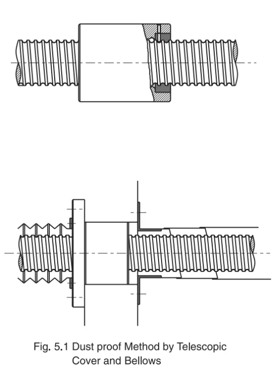
Any foreign matter or water, if allowed to enter the ball screw, may increase friction and cause damage. For example, the entry of chips or cutting oil may be expected with machine tools depending on the work environment. Where entry of foreign matter is anticipated, use a bellows or telescopic cover as shown in Fig 5.1, to cover the screw shaft completely.
5. Ball Screw Selection Matrix
Ground & Rolled Ball Screw Availability Matrix
| Dia. | Lead (mm) | ||||||||||||||||||||
|---|---|---|---|---|---|---|---|---|---|---|---|---|---|---|---|---|---|---|---|---|---|
| 1 | 2 | 2.5 | 2.54 | 3 | 4 | 5 | 5.08 | 6 | 8 | 10 | 12 | 15 | 16 | 20 | 24 | 25 | 32 | 40 | 50 | 64 | |
| 4 | |||||||||||||||||||||
| 6 | |||||||||||||||||||||
| 8 | |||||||||||||||||||||
| 9 | |||||||||||||||||||||
| 10 | |||||||||||||||||||||
| 12 | | | | | |||||||||||||||||
| 14 | |||||||||||||||||||||
| 15 | |||||||||||||||||||||
| 16 | |||||||||||||||||||||
| 19 | |||||||||||||||||||||
| 20 | |||||||||||||||||||||
| 25 | | | | ||||||||||||||||||
| 28 | | ||||||||||||||||||||
| 32 | | ||||||||||||||||||||
| 36 | |||||||||||||||||||||
| 38 | |||||||||||||||||||||
| 40 | | | |||||||||||||||||||
| 45 | | ||||||||||||||||||||
| 50 | |||||||||||||||||||||
| 63 | |||||||||||||||||||||
| 80 | |||||||||||||||||||||
| 100 | |||||||||||||||||||||
Need the full selection procedure matrix and dimensional diagrams?
Download Full PDF Catalogue (4.1MB)